Edge Commands
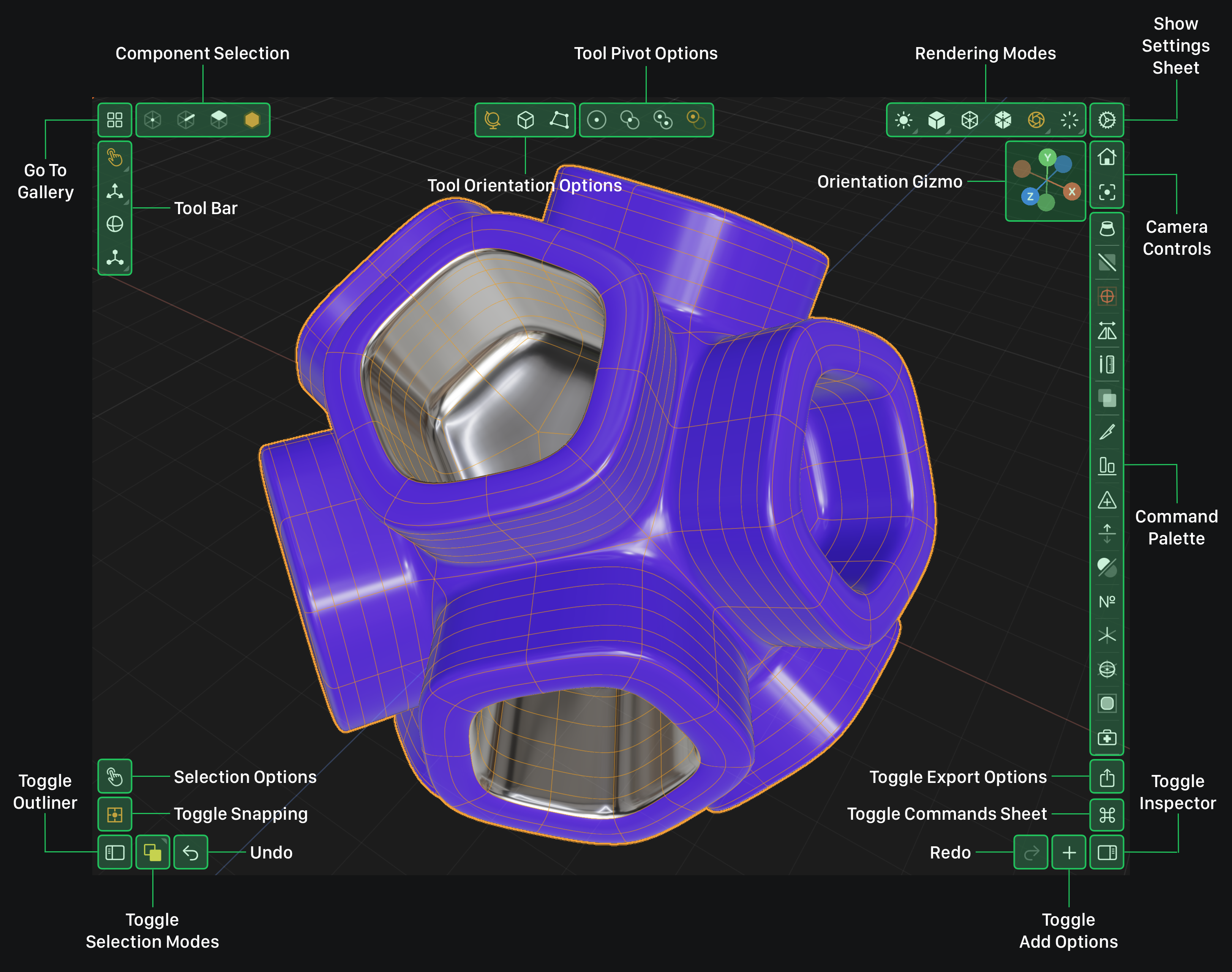
These commands allow you to perform complex operations on edges. For example, you can extrude an edge by using the Extrude command. Or you can split an edge by using the Split Edge command. These command are found in the Command Palette when the Component Selection is set to Edge and you have a edge or multiple edges selected. The Command Palette is located on the right side of the screen right below the Camera Controls (see below).
Modeler Interface
Isolation Commands
Toggle Isolation
Toggle Isolation is a single command that isolates the selected mesh when the rest of the scene is visible, and restores the scene when you are already isolated. The button's icon and color tell you which it will do.
Tap this button to isolate (solo) the selected mesh and make the rest of the scene invisible and locked.
Tap this button to de-isolate and unlock the rest of your scene and make it visible again.
Selection Commands
Grow Selection
Tap this button to grow the selection.
Shrink Selection
Tap this button to shrink the selection.
Invert Selection
Tap this button to invert the current selection and select all connected edges that are not selected.
Select Shell
Tap this button to select all connect edges to the current selection.
Clear Selection
Tap this button to clear the selection.
Modifier Commands
Toggle Subdivision Modifier
One command both adds and removes the Subdivision Modifier. The button is red when the selected mesh already has the modifier, meaning tapping it will remove it.
Tap this button to add a subdivision modifier to the selected mesh.
Tap this button to remove the subdivision modifier from the selected mesh.
Toggle Mirror Modifier
One command both adds and removes the Mirror Modifier. The button is red when the selected mesh already has the modifier, meaning tapping it will remove it.
Tap this button to add a mirror modifier to the selected mesh.
Tap this button to remove the mirror modifier from the selected mesh.
Modeling Commands
Knife Tool
Tap this button to activate the knife and cut edges to create new faces, edges and vertices.
The knife's options are the same in every mode — see Knife Tool for what Include Start Point, Include End Point and Close Cut When Possible do.
Align Edge
Tap this button to activate alignment mode. Then tap or drag on another mesh to align the selected edge to that mesh's surface.
The ORIENT option in the Align sheet is on by default and rotates the selection to match the target's normal. See Align.
Fill Hole
Tap this button to fill the hole that is touching the selected edge.
Extrude Edge(s)
Tap this button to extrude the selected edge(s).
Loop Cut
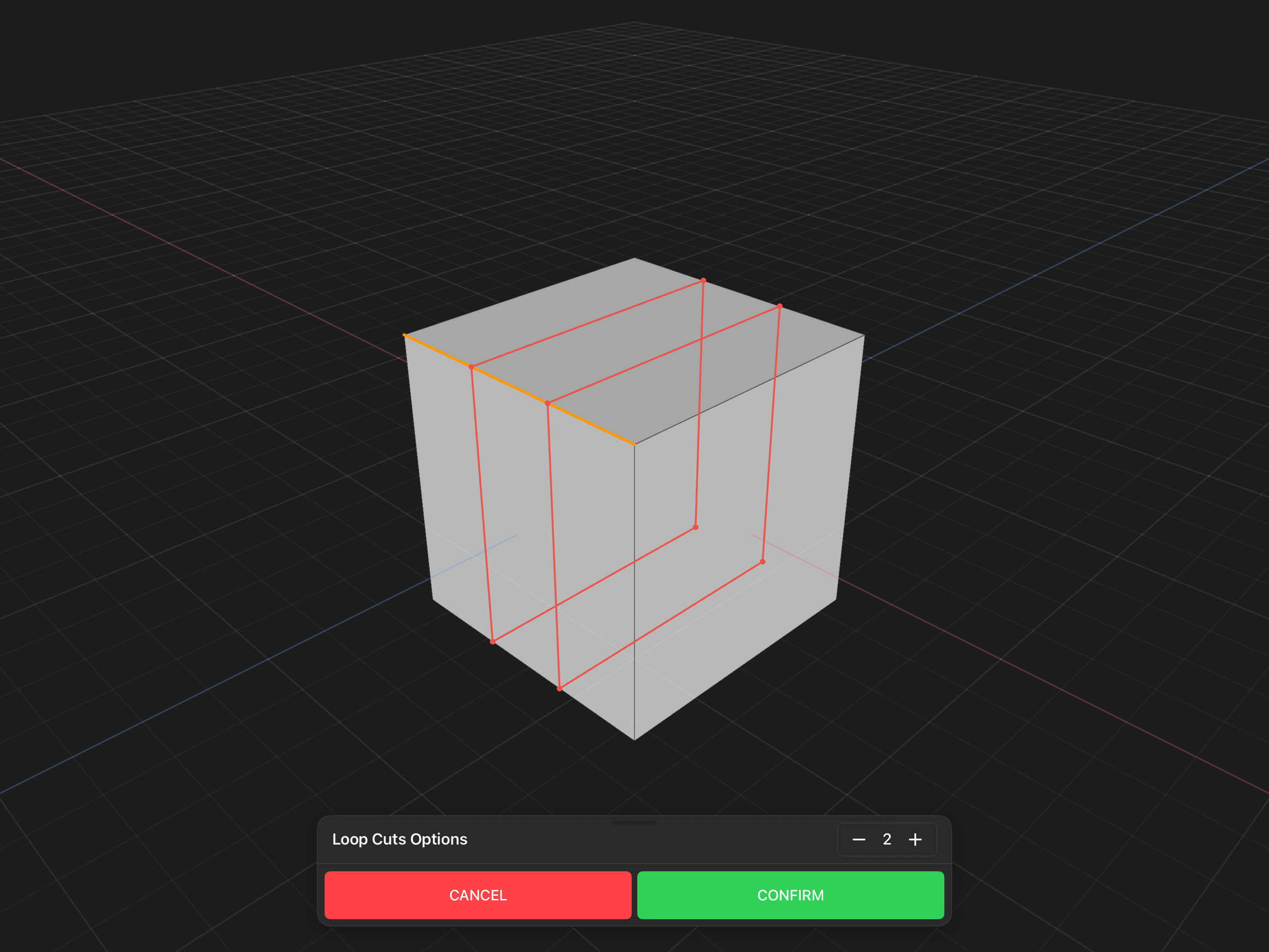
Tap this button to create mulitple loop cuts around the selected edge.
The Loop Cuts Options sheet has a stepper that sets how many evenly-spaced loops to insert around the selected edge's loop. It accepts 1 to 1000 cuts.
Loop Cuts Options
Split Edge(s)
Tap this button to split the selected edge(s), inserting a new vertex at the midpoint of each.
Bridge Edges
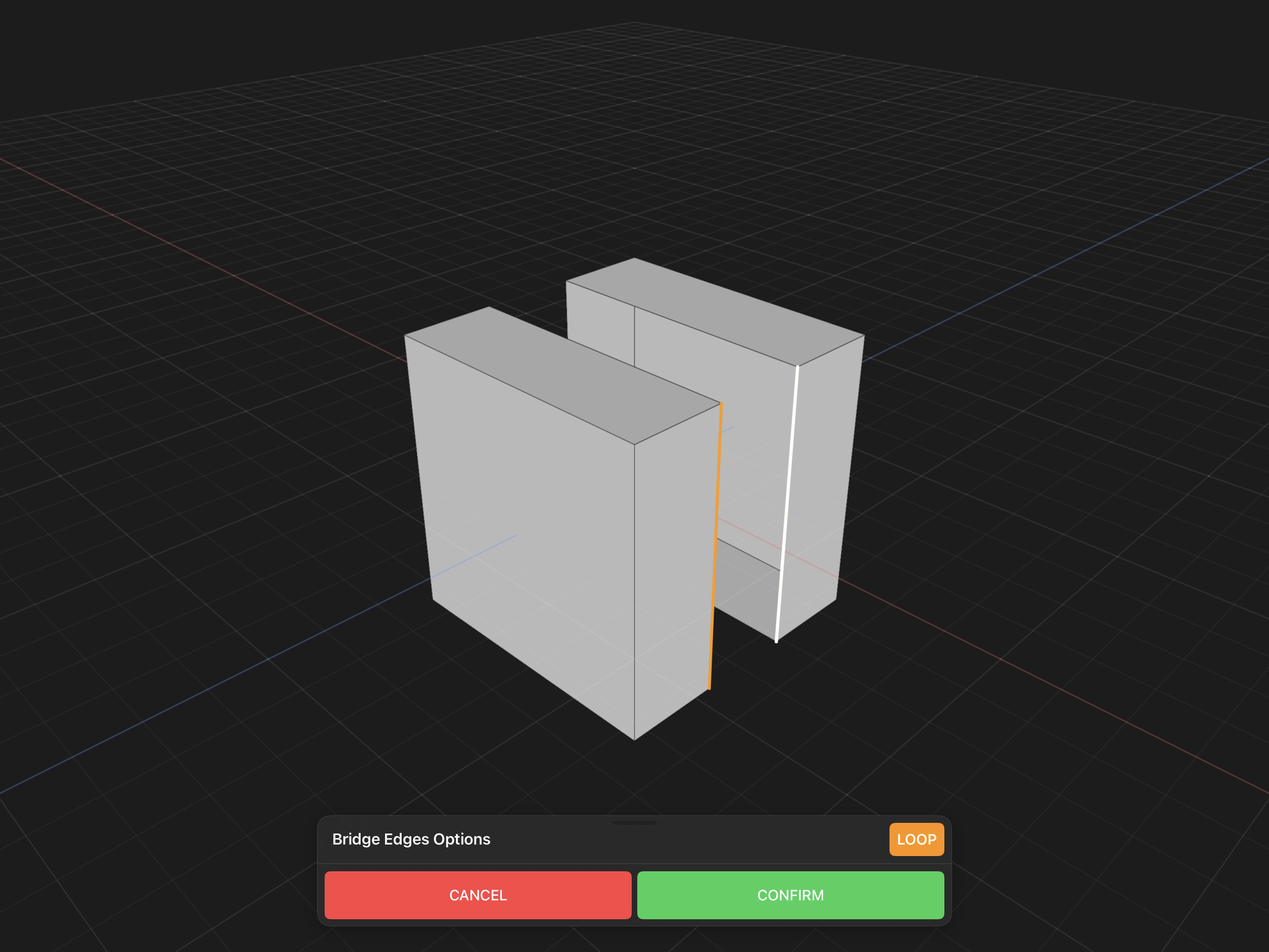
Tap this button to bridge the selected edges.
Bridge Edges only shows up when you have exactly two boundary edges selected (edges along the open border of a mesh).
The LOOP option in the sheet's header is on by default. When LOOP is on the two edge loops containing the selected edges are bridged, producing a ring of faces. Turn it off to bridge only the two selected edges.
Bridge Edges Options
Shading Commands
Harden Edge(s)
Tap this button to harden the selected edge(s).
Soften Edge(s)
Tap this button to soften the selected edge(s).
Destructive Commands
Delete Edge(s)
Tap this button to delete the selected edge(s).
Dissolve Edge(s)
Tap this button to dissolve the selected edge(s).
Collapse Edge(s)
Tap this button to collapse the selected edge(s).