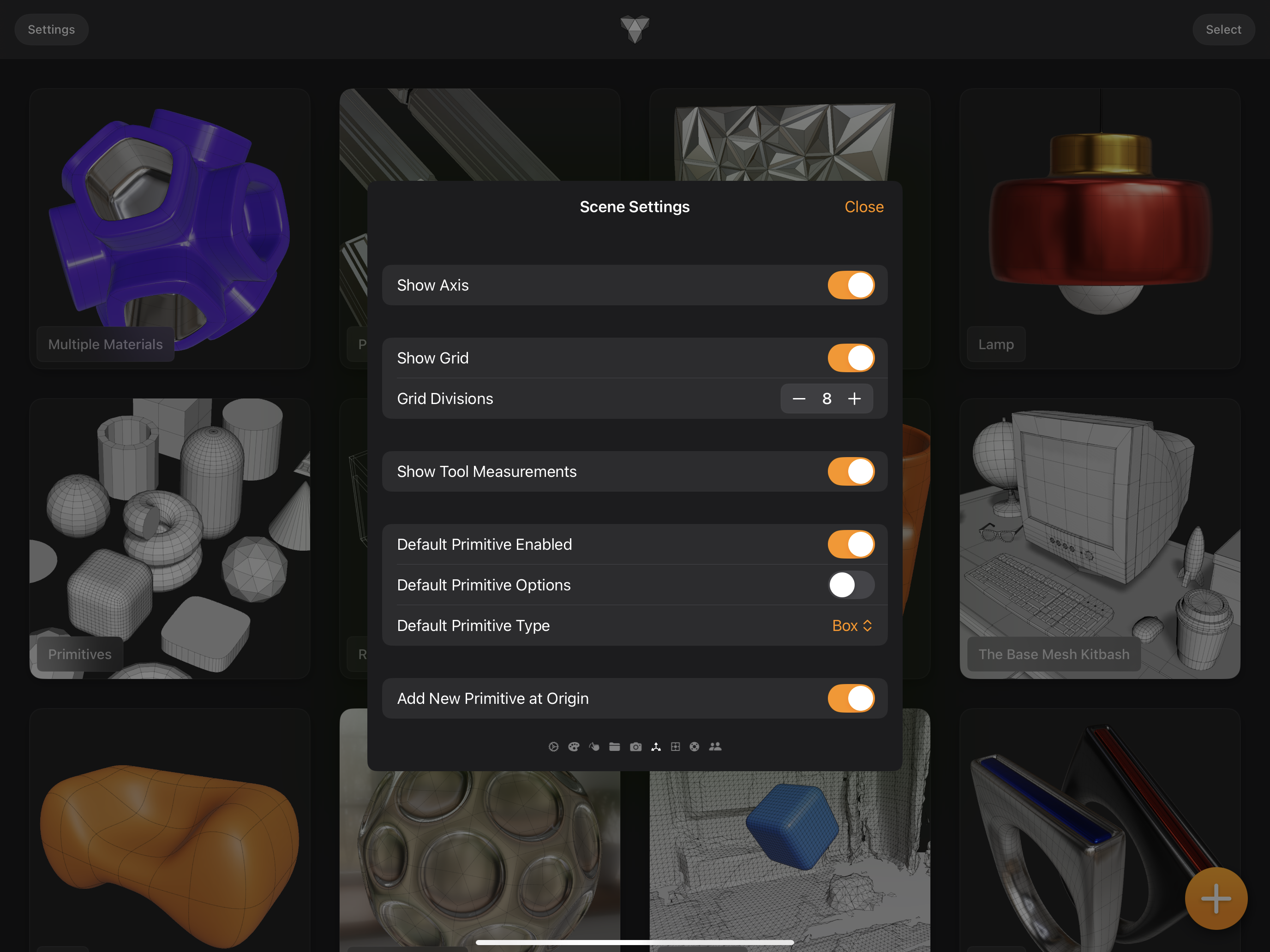
Scene Settings
When modeling in Valence 3D, the Modeler view displays a grid and axis to help you orient yourself in space and stay grounded. There are various scene settings that can be turned on and off to customize the modeling experience to suite your needs. These settings are grouped under Scene Settings page in the Settings sheet.
Settings Sheet
Show Axis
By default, Valence 3D is set to show the right (x-axis), up (y-axis) and forward (z-axis) axes. These axes are represented by thin colored lines that meet at the origin. The x-axis is red. The y-axis is green. The z-axis is blue.
Perspective Modeler View (Axes & Grid)
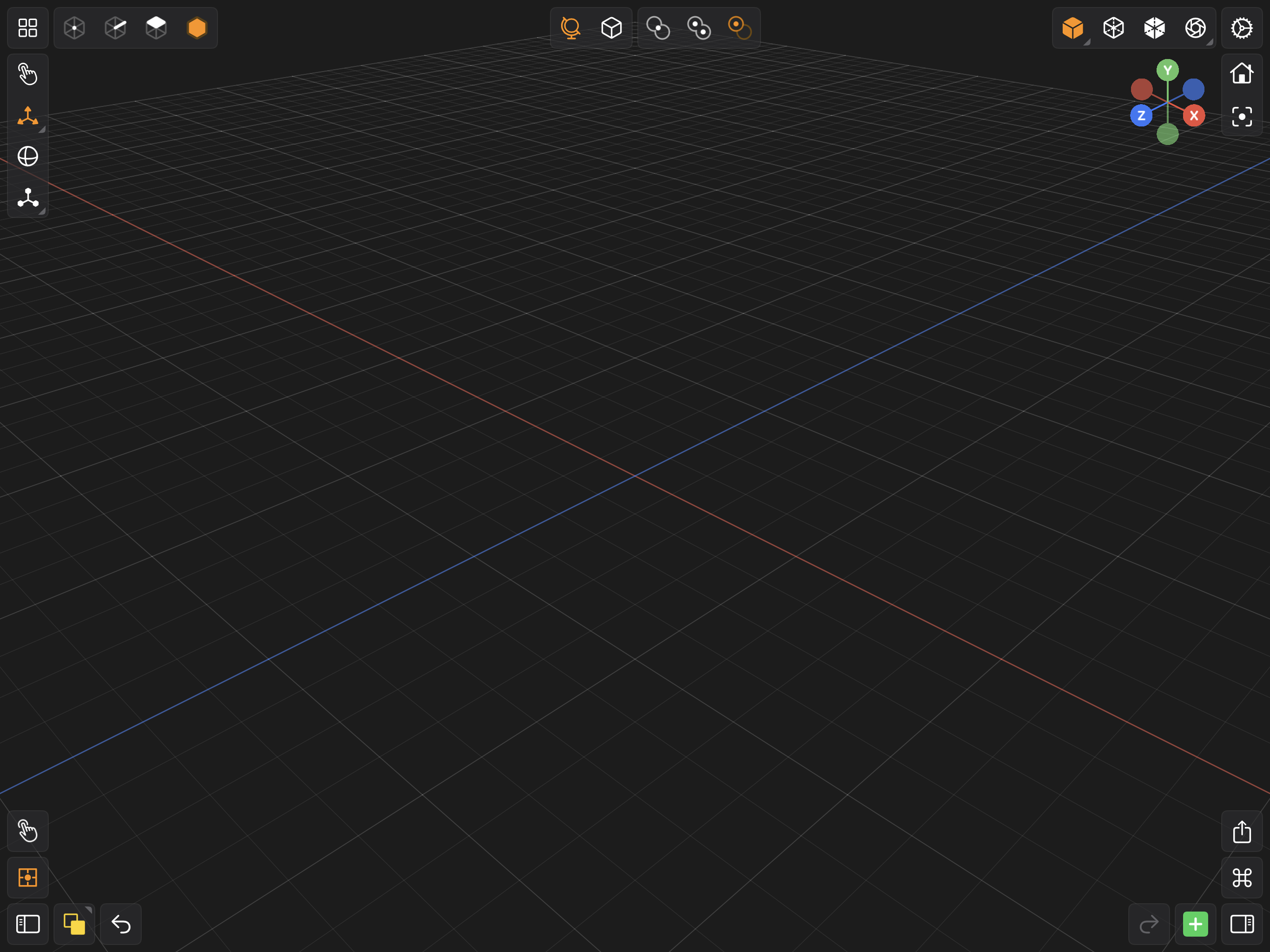
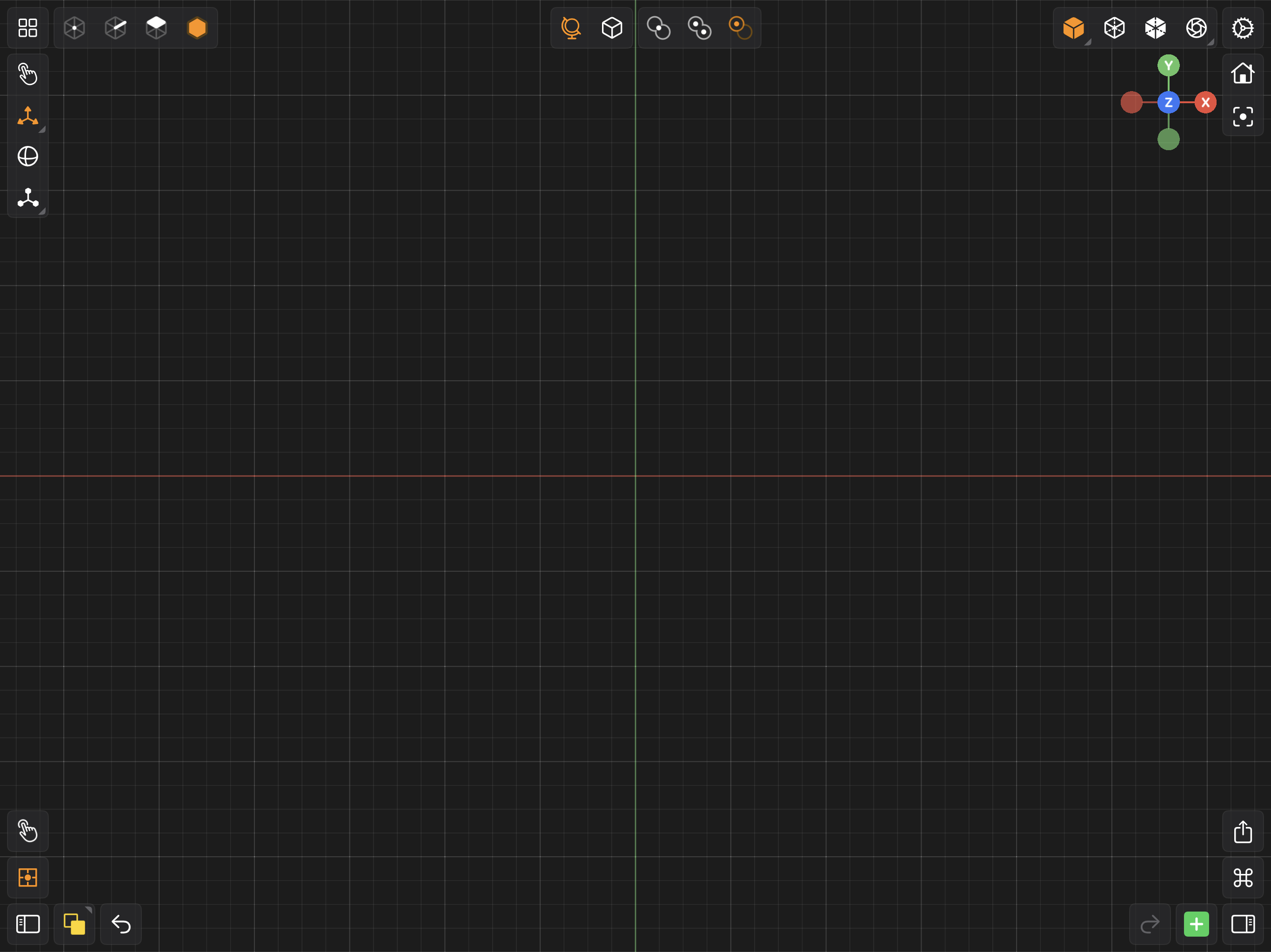
When viewing your scene in 3D the y-axis is invisible. When viewing your scene in one of the orthographics views (front, back, top, bottom, right, left) two out of the three axes will be visible. If you prefer not to see these axes while modeling, you can set the Show Axis toggle to OFF.
Show Grid
By default, Valence 3D is set to show the Grid. The Grid is composed of lines equally spaced 1 unit apart. The major grid lines are less transparent (more opaque) that the subgrid lines. The number of subgrid lines are configurable by the Grid Interval stepper in the SCENE settings. You can hide the grid by setting the Show Grid toggle to OFF.
Orthographic Modeler View (Axes & Grid)
Grid Divisions
The Grid Division setting determines the spacing between each subgrid line (which are more transparent than the major grid lines). To calculate the spacing between each subgrid line, the formula is as follows: 1.0 / Grid Divisions. So if you have 4 grid divisions, which is the default, then the space between each subgrid line is 1.0 / 4.0 or 0.25. To increase or decrease the number of subgrid divisions, use the + or - buttons to the right of the Grid Divisions label.
Show Tool Measurements
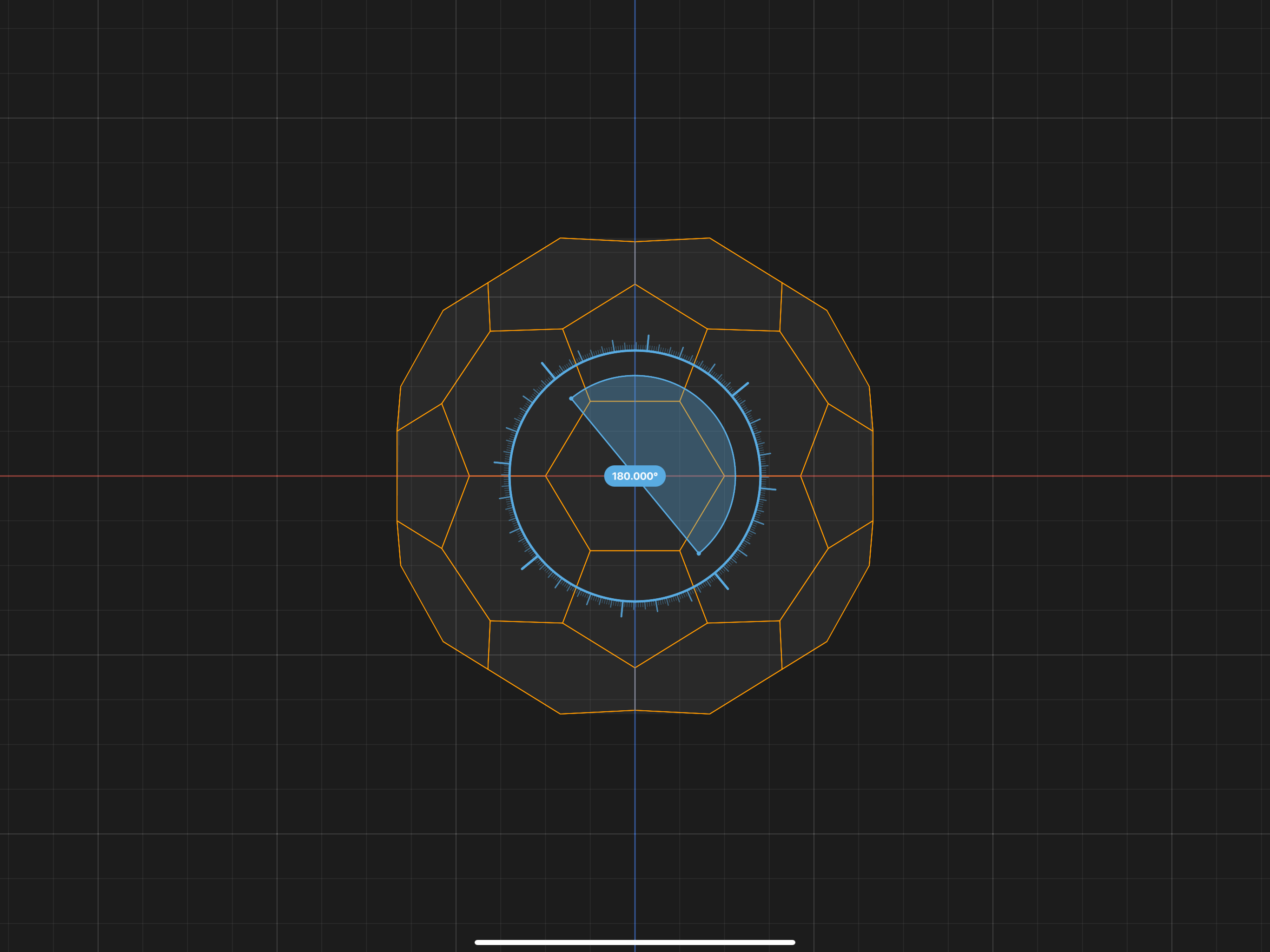
Whenever you use a tool to move, rotate, scale, extrude, etc, by default Valence 3D will show a visual helper that displays how far you have translated, rotated, scaled, extruded, etc. For example when rotating an object, you'll see a visual helper (shown in cyan below) that shows how much you have rotated. Each tool has a slightly different visual helper that shows its measurement. You can turn off these visual helpers by setting the Show Tool Measurements toggle to OFF.
Rotate Tool Measurement (Visual Helper)
Primitive Enabled
By default, Valence 3D is configured to add a box primitve into your scene everytime you open a new file. You can disable this behavior by setting the Primitive Enabled toggle to OFF.
Primitive Options
By default, Valence 3D is configured to NOT show the default primitive's options when a new file is opened. However, if you find yourself wanting to configure the default primitive when it appears in the scene, you can enable Primitive Options by setting its toggle to ON. When Primitive Options is enabled after opening a new file, you'll have the option to future customize the default primitive added.
Primitive Types
By default, a Box primitive is added to a new file when its opened. You can customize which primitive is added by using the drop down menu to the right of the Primitive Type label.
Default Primitive Types
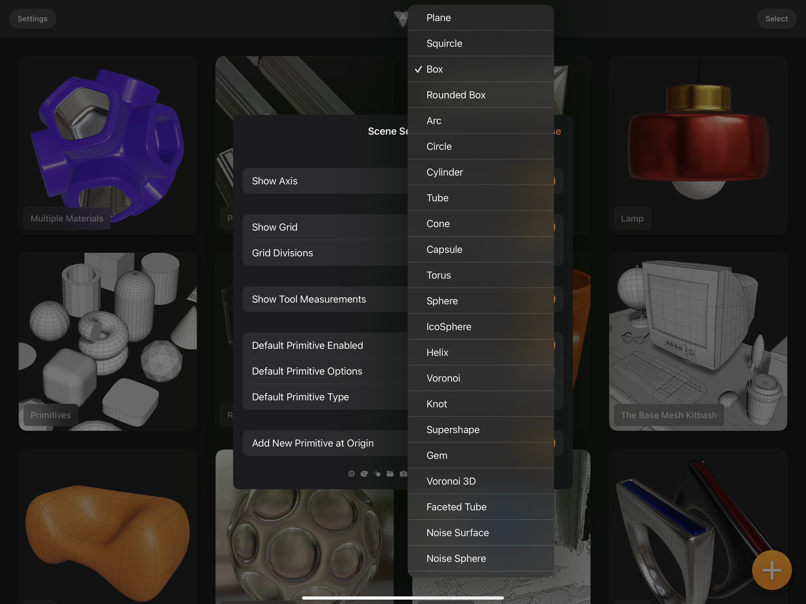
This is complete list of the procedural primitives in Valence 3D:
Primitive at Origin
By default Valence will place new primitives at the origin of the scene. If you'd like to have Valence 3D place a new primitive in front of the camera instead, toggle Add New Primitive at Origin to OFF and Valence 3D will then place the new primitive in world space in front of the camera.